-
Notifications
You must be signed in to change notification settings - Fork 56
Configuring touchscreens
OpenDeck firmware currently supports touchscreens from Nextion. The way these touchscreens are controlled is via simple serial commands. They also come with easy to use graphical user interface used to create touchscreen layout. Each Nextion touchscreen has the same instruction set and as far the way they are controlled is concerned, they are all the same. For this reason OpenDeck firmware supports the entire Nextion line. They come in various sizes and most of them are available as both resistive and capacitive models.
Note: My own experience has shown that for at least DJ purposes, resistive touchscreens are better than capacitive ones. For this kind of need, quite often fast-paced movements towards touchscreen are required to quickly toggle something on or off. Normally when this action is performed, finger is also quickly lifted from the touchscreen. Sadly, capactive touchscreens have issues registering that - often this kind of movement is done without finger being fully on the touchscreen so that it can be registered on capacitive touchscreen, however, on resistive screen the only thing that matters is the pressing force, therefore, they have no issues with registering those kinds of movements.
Currently supported features on these touchscreens are:
-
Buttons - touch areas can be defined on touchscreen which then represent buttons in OpenDeck firmware. The firmware makes no distinction between regular, physical buttons and touchscreen buttons - every single feature which is available for normal buttons is also available for touchscreen buttons. For official OpenDeck board, total supported amount of touchscreen buttons is hardcoded to 64. Web interface will simply append total number of supported touchscreen buttons to the total number of supported physical buttons, so configuration is exactly the same as for physical buttons.
-
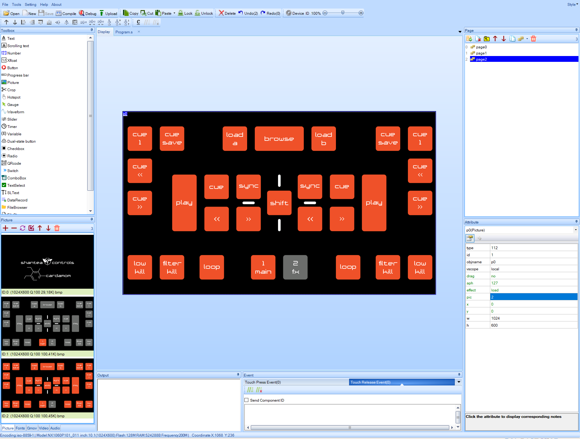
Indicators - Images on touchscreen can be designed in a way so that there's an "off" page and "on" page. Off page contains elements in "off" state and "on" page contains elements in "on" state. This scheme can be used to simulate LED behavior. It's important that the elements on both pages are in equal X/Y coordinates in order for this feature to work correctly. See images for Cardamom controller as an example of this. As with buttons, firmware makes no distinction between physical LEDs and indicators on touchscreen, so all available LED options (except for fading and RGB) are also available for touchscreen indicators. As with buttons, Web interface will simply append total number of supported touchscreen indicators to the total number of available LEDs, so configuration is exactly the same as for physical LEDs.
To start creating the interface for these touchscreens, first download the Nextion editor. Sadly the editor is available for Windows only. All my attempts to make it run through WINE have failed, so Windows is a hard requirement for this.
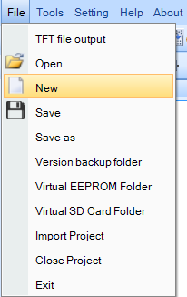
Once the editor is installed, create a new project from the File menu.

On the next screen, choose your Nextion model and touchscreen orientation.


After these steps are done, blank project is created. To add images to the project, click on + sign in the Picture section below the Toolbox. Make sure the added images have the same resolution as the touchscreen which is being used.

After the images have been added, they will be shown in the same section.

Click on Program.s tab right next to the Display tab.

Paste the following code in this section:
//The following code is only run once when power on, and is generally used for global variable definition and power on initialization data
int sys0=0,sys1=0,sys2=0     //At present, the definition of global variable only supports 4-byte signed integer (int), and other types of global quantity declaration are not supported. If you want to use string type, you can use variable control in the page to implement
bauds=38400
baud=38400
page 0                       //Power on start page 0
This will ensure that the correct baud rate is set once the touchscreen is turned on.
Nextion editor has the concept of "pages". Each page is actually a screen on the touchscreen. By default, a single, blank page is created automatically for each new project called page0.

Click on + sign on the "Page" section to add new page or just edit the first one. Make sure to set sta atribute to no background. Otherwise, touchscreen will first load background and then user image which will slow down its response.

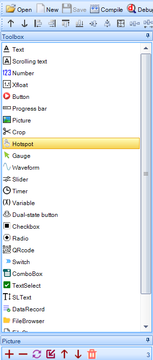
To add a picture to a page, click on "Picture" element in the toolbox.

Picture element called pic0 will be selected by default. Click on pic attribute to select the picture this element will contain and select one of the previously added pictures. Once that is done, full-screen image will appear.

To add a button to a page, click on Hotspot element in the toolbox.

New element will appear on the page called m0 which can be dragged around and resized. Place it in a location where your button is located and size it properly.

Make sure that Send component ID option is turned off for both Touch press event and Touch release event.
In order to make this element act like a button in OpenDeck firmware, a custom command is used which must be typed in both Touch press event and Touch release event text boxes.
For touch press event, the following command shall be used:
printh 65 01 button_index ff ff ff
For touch release event, the following command shall be used:
printh 65 00 button_index ff ff ff
button_index string should be replaced with actual button index in hex format, ie. for button 0 press/release messages should be:
- press:
printh 65 01 00 ff ff ff - release:
printh 65 00 00 ff ff ff
For button 10:
- press:
printh 65 01 0A ff ff ff - release:
printh 65 00 0A ff ff ff
etc.
Make sure button index is unique for each added Hotspot element.
To make indicator/LED simulation work, a new page should be added with picture element. The image must have exact same layout as the original image, just with elements in either on or off state, depending in which state they are in the first image.

There is nothing else to configure in the editor for this feature to work.
Uploading can be done either via USB to serial converter or via microSD card.
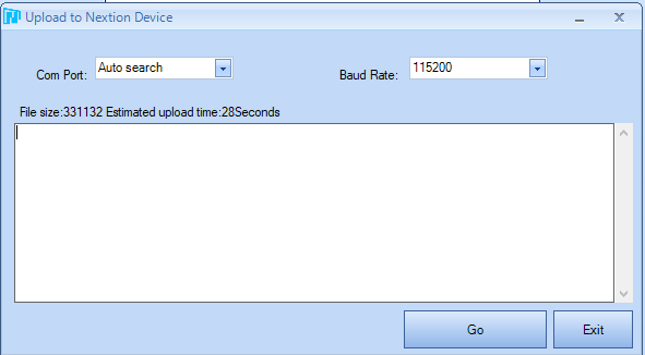
Click on upload button in the toolbar.

A new dialog will appear. COM port on which the touchscreen is connected should be selected. Set the baud rate to 38400.

A USB to serial device is needed in order to connect the touchscreen to the PC. STM32-based OpenDeck boards (official OpenDeck boards, Black Pill boards, STM32F4Discovery) support CDC mode in which the board acts as serial bridge. AVR boards (Arduino Mega, Teensy++ 2.0) don't support CDC mode so you have to use USB to serial converter or microSD to flash the touchscreen. Note that the touchscreens work normally with AVR boards after they are flashed. CDC mode can be used to achieve communication with Nextion GUI and touchscreen and can be enabled via the Web interface. For other boards, recommended way of connecting the touchscreen to a serial port is using the CP2102 USB module, but any other TTL UART module will work as well.
- If using USB to serial converter: Connect RX signal from touchscreen to TX pin on UART converter. Connect TX signal from touchscreen to RX pin on UART converter. Connect touchscreen to external power supply. Make sure touchscreen and converter share the same GND.

- If using OpenDeck board with supported CDC mode: follow the connection guide for your board on this page.
Use any microSD card with the maximum capacity of 16GB. If you have larger microSD card, create a single partition on in with maximum capacity of 16GB. Card must be formatted to FAT32 file system. Click on File in toolbar, and then select TFT file output. Save the TFT file to microSD. Turn off your touchscreen, insert the card to the touchscreen, turn it on and wait until upload is finished. Once finished, turn off the touchscreen, remove the card and turn the touchscreen on again.
Last step before using the touchscreen is to enable it in the web interface.

Hardware
- Supported microcontrollers
- Supported components
- Pinouts for supported boards
- Recommended components and where to get them
- LED indicators
Configuration and usage
Advanced